GPU Ray tracing
GPU Ray tracing is supported. It enables high-speed and high-quality image generation by performing ray tracing on the GPU, unlike the conventional real-time rendering using the CPU.
Advanced expressions such as refraction of transparencies, object reflection, and global illumination can be checked in real time.
In addition to previewing in drawings, it can also be used as a final rendering, dramatically speeding up the production of any genre.
*OS and GPU that support GPU Ray tracing are required for operation. Please check the System Requirements of Ver.22 for further details.

GPU Ray tracing benchmark
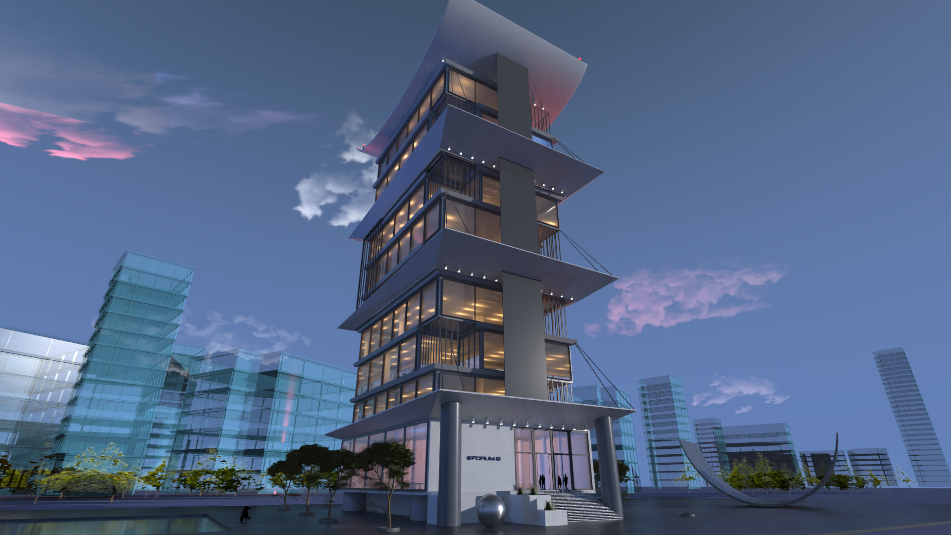
- ■ Rendering time
- 2 seconds
- ■ Measured scene
- Rendering size: 1920x1080
- Number of light sources: 150
- Number of faces: 51082
- ■ Measurement environment
- OS:Windows 10
- CPU:16 x Intel(R) Core(TM) i7-10700 CPU @ 2.90GHz
- GPU:NVIDIA GeForce RTX 2070 SUPER 8GB
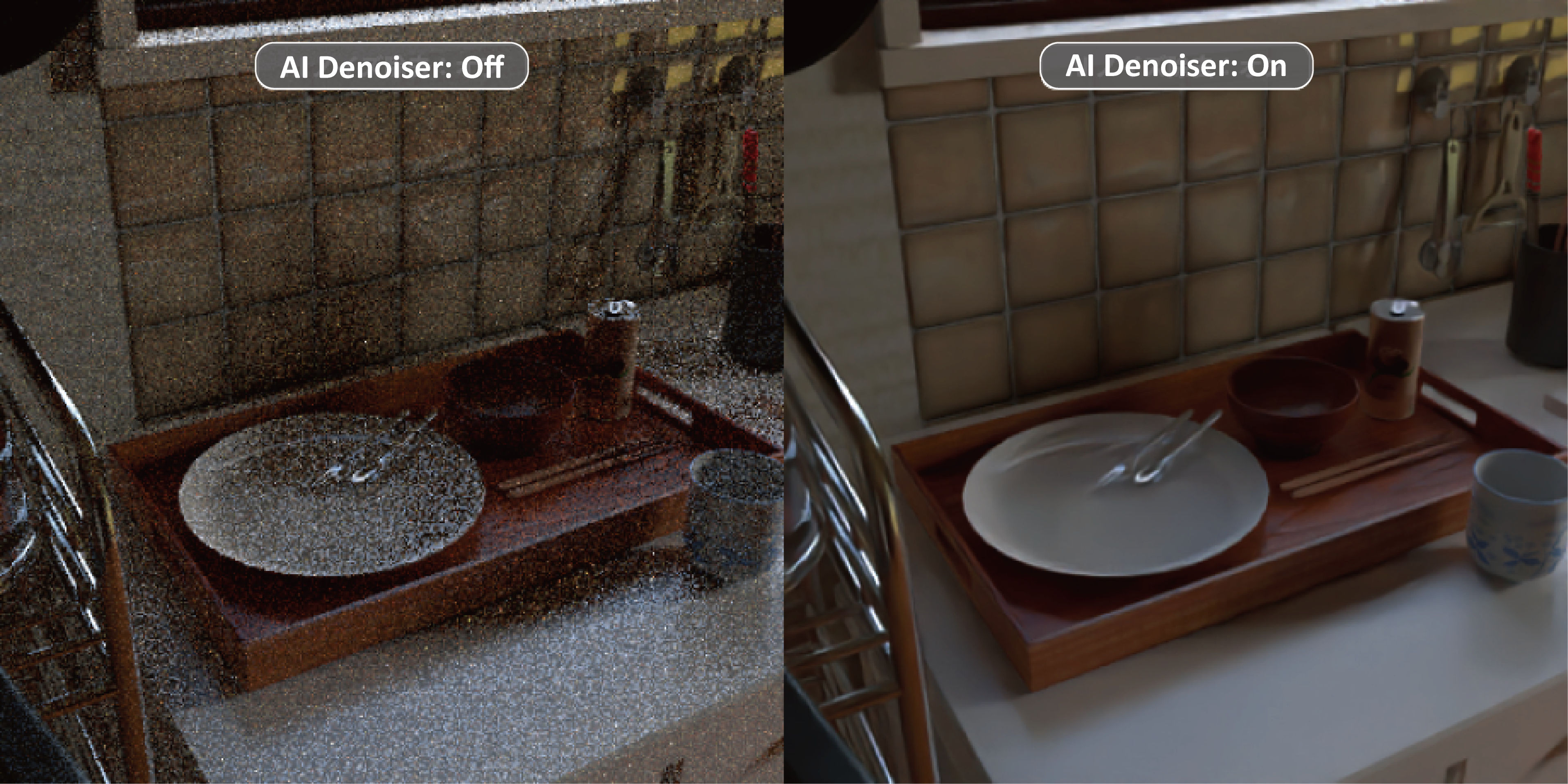
AI Denoiser (Intel(R) Open Image Denoise)
Equipped with a noise reduction library developed by Intel, and is capable of efficiently removing high-frequency noise through AI-based deep learning filter.
High quality, noise-free results can be easily obtained in a short time without the need for drastic settings.
Greatly effective for Global Illumination Path Tracing (without Irradiances Caching), shadow softness of light sources, Area Light, Linear Light, and roughness of surface materials.
Supports rendering using the Path Tracing method and GPU Ray tracing method.
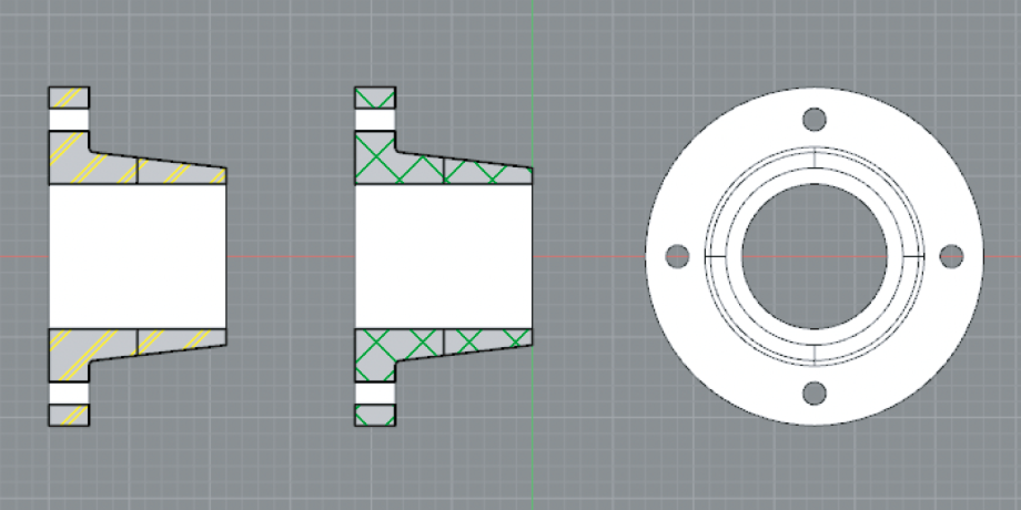
"Drafting" display mode in figure windows
Added a new "Drafting" display mode specialized for use as a drawing.
Supports line type, line thickness, color, and hatching of surfaces.
Supports both 2D and 3D drawings, allowing information to be expressed in accordance with 3D models.
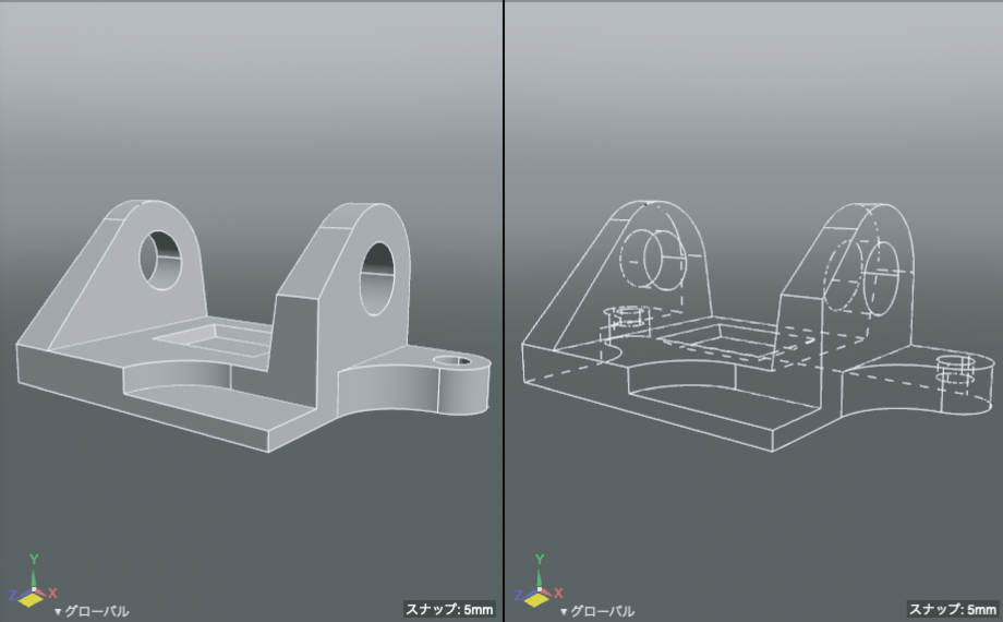
Display of hidden lines of wireframe
Added "Hidden Lines" mode, which displays hidden lines of wireframe as dashed lines in the drawing view.
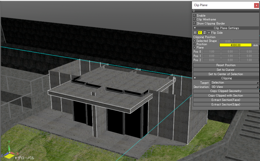
Support for clipping position by numerical input of coordinates
The clipping position can now be specified in absolute coordinates.
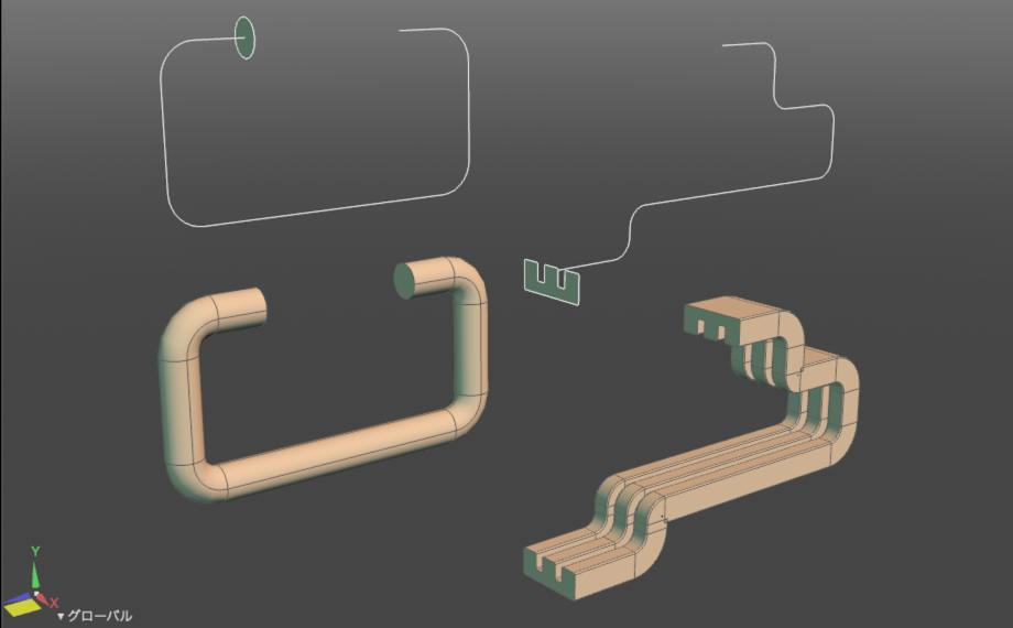
Swept Surface
Swept Surface is added as a new shape type.
The combination of a cross-section line and a reference line creates a new surface.
The changes are projected instantly. This function allows efficient creation and modification of Reinforcing bars, pipes, rails and other objects.
The reference lines can be circles as well as open lines. Easily adjusted for the intended use.
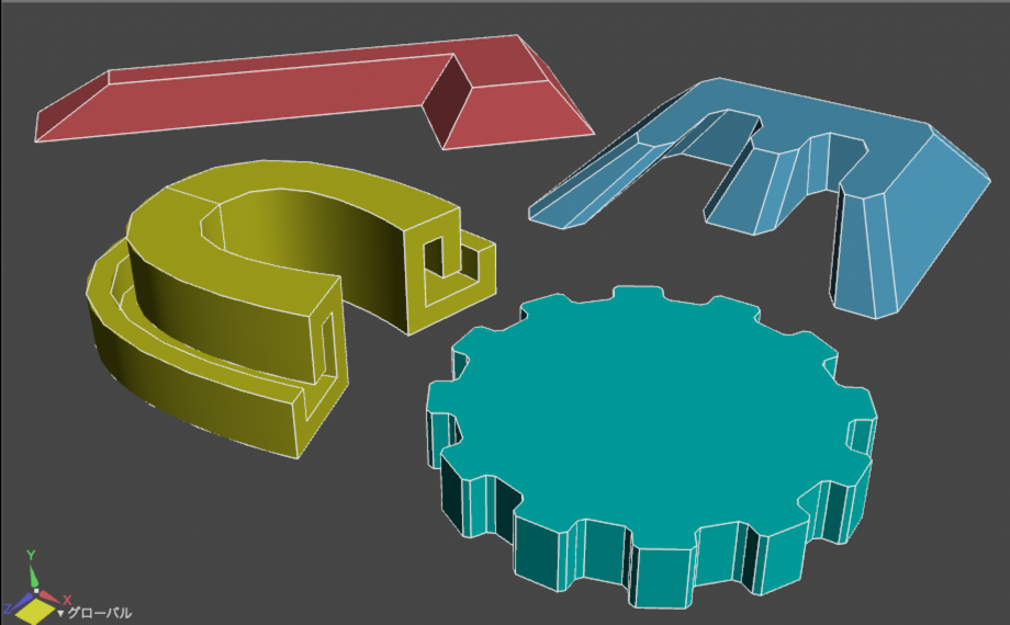
Closing Free-form Surfaces
Auto-geneted closing surfaces for the free-form surface is added.
Concave, convex, L-shape and other surfaces that does not converge to a point can be closed with one click.
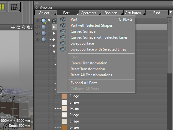
4 commands added to the "Part" Browser window
4 commands, "Clear", "Cancel Transformation", "Reset Transformation" , and "Reset All Transformations", are added to the browser of the "Part" pop-up menu.
Part conversion matrix editing functions in "Main Menu" > "Tools" > "Move" can be operated from the Browser window.
FBX2020 File Import 
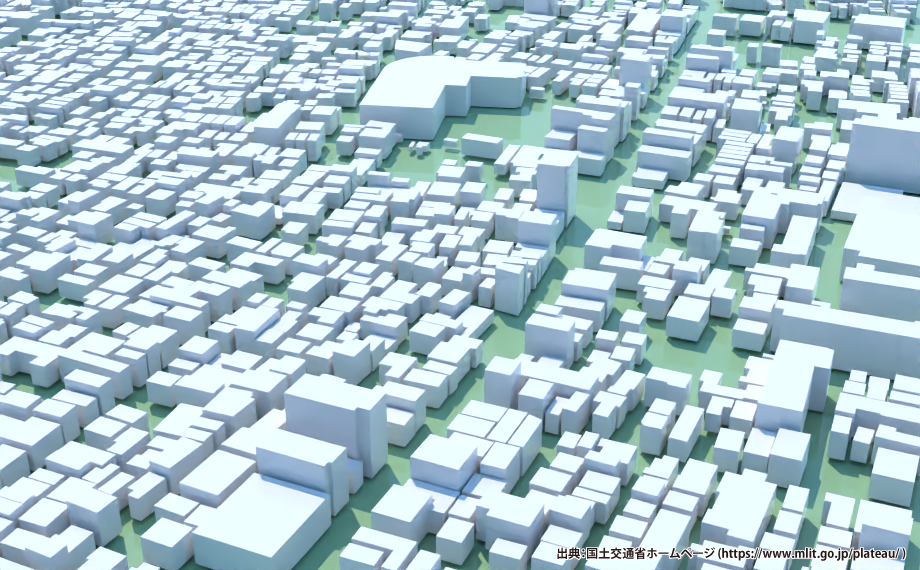
FBX2020 file format can be imported.
The latest data and file format can be imported including FBX files that can be downloaded from PLATEAU, a project led by the MLIT to develop, utilize and open data on 3D city models throughout Japan.
Enhanced DXF Import Function
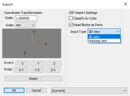
- The following existing features have been improved.
- "Classify by Color" checkbox
- Create a part sorted by AutoCAD Color Index (ACI) with reference to the defined color of the shape.
- “Read Block as Parts” checkbox
- When it is turned on, the blocks used in the drawing are read together in a part and placed in the LAYER part to which they belong. (The BLOCK name is reflected in the part name.)
When it is turned off, the shape of the block is directly placed in the LAYER part. - "Import Type" pop-up menu
- The drawing to be imported can be selected from "3D view" or "Drawing view".
- SPLINE shape can now be imported.
- Shape line color is now supported. It can be checked in “Drawing” display mode.
Improvement of BIM/CIM Design Check Tool
(Sold separately)
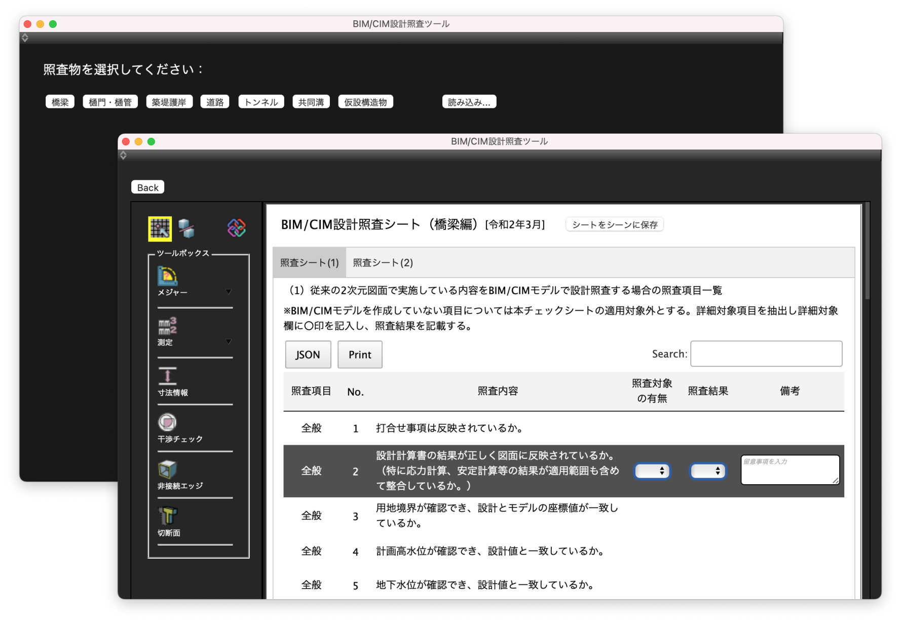
The interface has been redesigned and become more convenient.
- Display by step
- Tab-switching for verification sheets (1) and (2)
- Verification sheets (1) and (2) can be saved to a Shade3D scene.
- Verification sheets (1) and (2) can be saved to a JSON file.
Improvement of IFC input/output and editing function
(Sold separately)
- IFC import has been enhanced to support more model data types for import to Shade3D.
- IFC export now supports the model export, reflecting results of model editing in Shade3D.
- The attribute information editing function has been enhanced to support the creation, deletion, and assignment of attribute information for IfcProduct and IfcProject.
- Added settings of the external reference file path for text attributes (such as IfcText).
Shade3D now supports "Moving IfcProduct by moving part" and "outputting model data by editing polygon mesh". Each has a different effect on IFC files.
Moving IfcProduct
- Select the part where the interference occurs.
- Move the part to avoid interference.
- Export an IFC file with rebar model information.

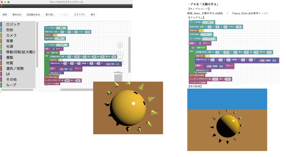
Added samples for Block UI Programming Tool
(Sold separately)
Samples for beginners have been added.
In addition to sample programs to learn how to use blocks, it includes application programs for intermediates.
The demonstration sample contents and the manual which can be used to explain the tool simply are also attached.
