


Create a character
- Modeling
- UV assignment
- Texture rendering (painting tools such as Photoshop)
- Bone allocation
- Skin allocation
- Motion setting
With larger division.
The goal is to create a character suitable to "modeling motion", it will be checked with MMD and Unity.
Lets start the Dragon's modeling.
Rules for Real Time Modeling
When exporting the modeling data to Unity and MMD in the fbx file format, some of the Shade 3D specificities won't be respected. Furthermore, as this is real time, make sure to respect the followings:
- Use a restricted number of polygons (low polygon)
- Be aware of triangle polygon
- 1 polygon mesh is one character
- The surface material mapping is designated by "image". Diffuse Reflection (diffuse), Gloss (specular), Normal (Nnormal), Roughness (roughness),are often used in real time
- Mapping images sizes are always square powers of 2 (16x16,32x32,64x64,128x128,256x256,512x512) A mapping of a surface material uses UV
- For the pixel transmission of a texture, in diffuse reflection, use a png image with an alpha
- Only single image is to be allocated for mapping layer such as diffuse, specular, normal and roughness
- Bone's route is 1
- Bone's transformation matrix: Scale is 1,1,1 Rotation and Shear are 0,0,0
Even though today it is not rare to see human body models made of tens of thousands of polygons, it is always best to create objects with less polygons as possible.
While you are modeling, keep in mind the triangle's divisions. 65535 triangles is the limit in Unity.
As the default export to fbx converts to triangles or squares, you do not need to care about modeling in triangle shape all the time.
While working in Real Time, you always need to keep in mind how "heavy" your character will be, therefore, you need to optimize it.
Concerning the mapping of the surface material, as often as possible, keep only one element for the texture.
For each tips, an explanation will be included.
Modeling
Here is the procedure you should follow to create a polygon mesh when you want to export it to other tools (e.g. using the fbx file format).
Assign a Sketch to a Template
Here, we are going to use a sketch of a Dragon's side view. As rough as it is, it is still OK for the modeling.
In this screen, let's place the sketch's side view in the Right View of the viewport (Template>Load Image).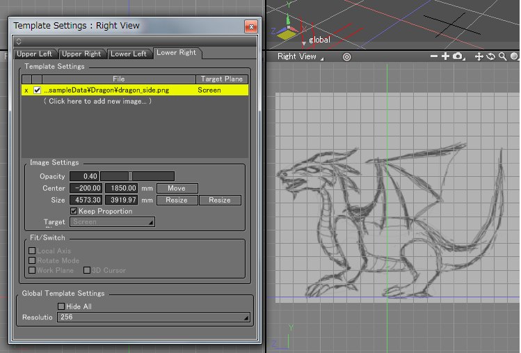
You can edit your image in the "Template Settings" window (opacity, size, position).
Polygon Mesh Modeling
Please use the following procedure.
- Create a "shell"/"an "Empty polygon object polygon mesh" (Create>Mesh)
- Outline the edge of the figure/sketch
- Create the surface by extruding the outline
- Keep adding surfaces in order to shape your Dragon, only the left side will be created first
- Generate the right half with the mirror tool
Modeling half of the model reduces the modeling time by half.
To start the low polygon modeling, repeat the face modeling technic.
*Here the perspective view is used as the main modeling view. You can also use a pen tablet if you feel more comfortable with it.
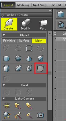
Create an "Empty polygon object polygon mesh" (Create>Mesh)
In the toolbox's Create > Mesh tab, click "Create an empty polygon object". A "Polygon Mesh" will appear in the Browser on the right hand side.
Create the outline
Select your "Polygon Mesh" (in the Browser), enter the Modify mode (M) and select "Add edges to polygon mesh", then, follow the sketch's outline.
First place the sketch in the side view.
In the Front View, you will move slightly the created outline on the x axis in order to align it on the center.
Note that the side lines (body and face) are important as a point of reference for your dragon's width (keep also in mind that the model will be mirrored).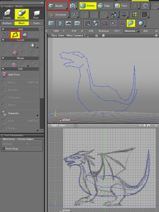
In order to see and move your verteces, you can enter the "Modify" mode and select the "Vertex selection" icon.
Extrude the outline and create the surface
In the Modify mode, select the "Edge selection" icon and in the "Modify>Mesh>Edit" section of the toolbox, select the "Extrude Selected Face or Edge" tool. Then, in the Top or Front view click and drag the cursor to the right side in order to obtain the desired extrusion.
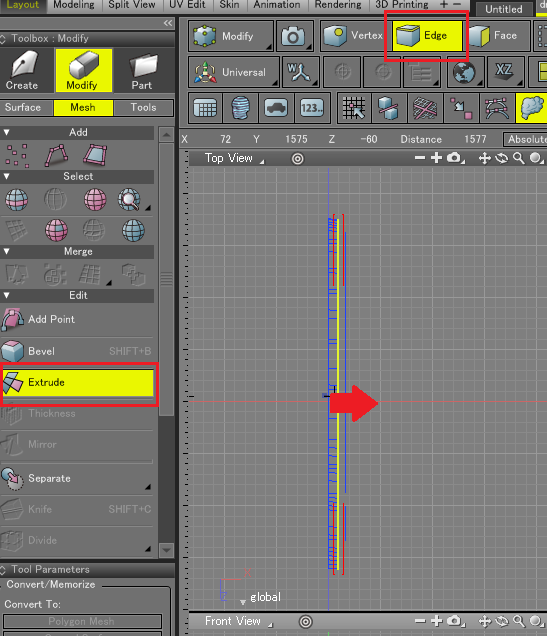
Now, by rotating the polygon mesh in the perspective view, it is easier to see the shape of your model.
Keep stretching the surface in the Perspective view
Your model in the Perspective view should look like the picture below: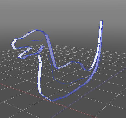
Tips
In the Menu of the Perspective view (small sphere in the upper right corner), you can select the "Double Side" option (Display>Double Side). in order to see which direction the faces are facing (turned IN and OUT).
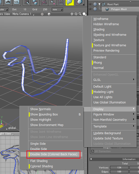
The back faces have a bluish color.
In the polygon mesh modeling, being able to see the front and back of the faces is very important.
For optimization matters, in the real time applications, the back of the object's faces are not displayed
Also, if you are trying to create a surface by connecting the vertices in a "counter clockwise way", the surface will be reversed by default.
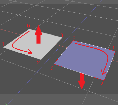
I the surface is flipped, in the Modify mode + Face selection, selecting "Normals" allows you to:
- Unify the normals
- Flip the normals
Tips : Optimizing Perspective view Modeling Technique
When modeling in the perspective view, click on the small arrow in the lower right corner and select the "Screen" option.
In the perspective view, by clicking while holding the space key, you can move your figure and by holding the space key + shift, you can rotate it. 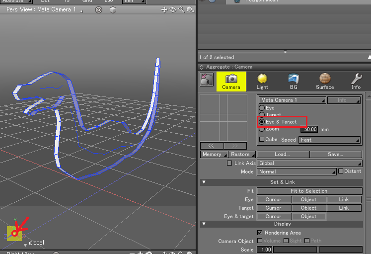
As you might have to often change the camera views, you should get used the fillowing technique:
If you want to re-center the view on your object during the modeling, click the "Fit" (target looking icon) button in the perspective view.
In the normal mode, the Fit button will center the view on your object, in the Modify mode, it will focus on the selected vertex/edge or face.
It is very convenient if you have lost sight of the wanted point during the modeling.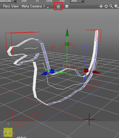
Furthermore, it is better to turn OFF the grid snap during the modeling in the perspective view.
Only on half is modeled, you will adjust the missing half with Mirroring.
In the Modify mode, it is easy to progress vertex by vertex.
While stretching the surface,in the Modify mode (Mesh>Add) you can use the "Add faces to polygon" and "Add edges to polygon".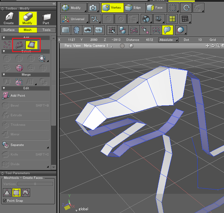
While using the "Add faces to polygon mesh" method, it is more convenient to work with rectangle faces.
My advice is to feel relaxed and follow your imagination. When you do modeling, you don't have to be too afraid of placing wrong vertices while creating faces. This is simple repetition of changing camera angles and creating faces.
If you find a point where vertices do separate from each other, you can fix it by selecting them and using "Merge Points" command.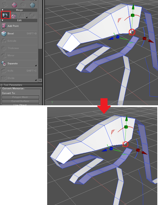
When a vertex moves during a camera movement, you can readjust it with the Manipulator.
In the Edge selection mode, you can use the Loop Slice tool of the Edit mode (you will click the selected edge in order to slice it).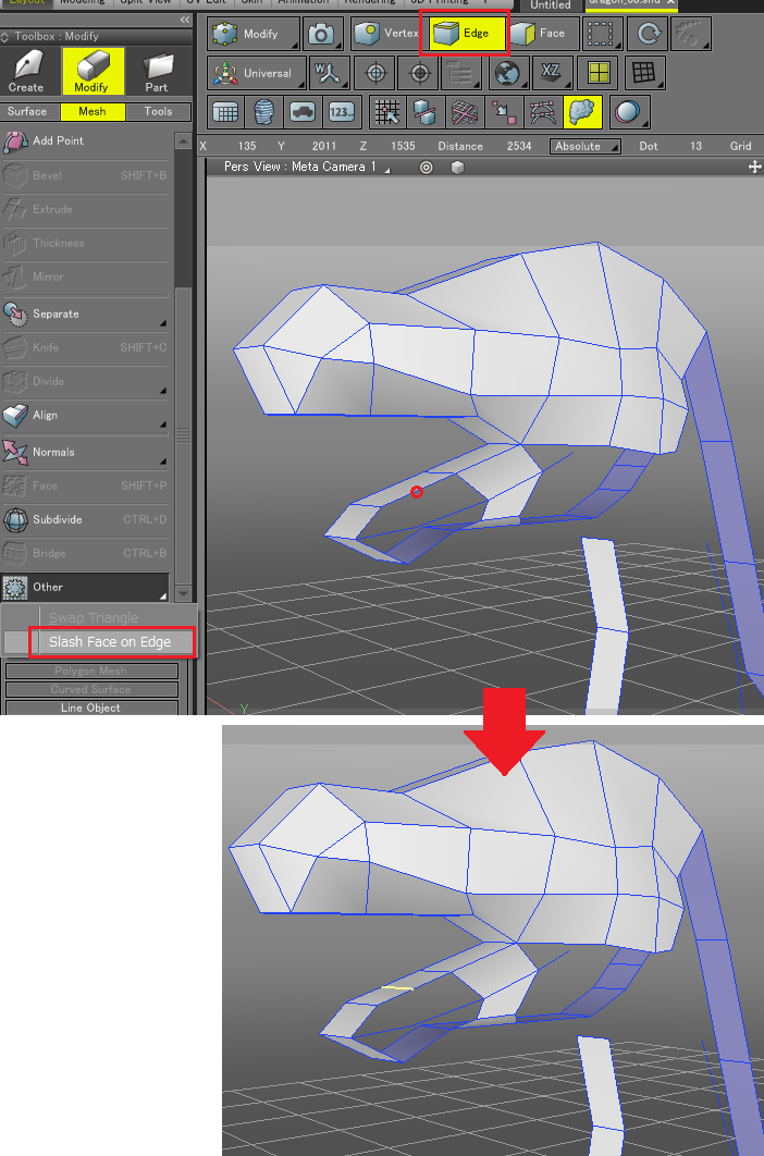
If you want to split an edge, you have to drag the cursor through the edge you want to split while holding [Z][X] on Windows and option + command on a Mac.
Tips : To do a panning operation in the perspective view
By default, the position of the camera object in Shade 3D is set to "Normal". In the example below, we set the camera object to the "Free" Mode.
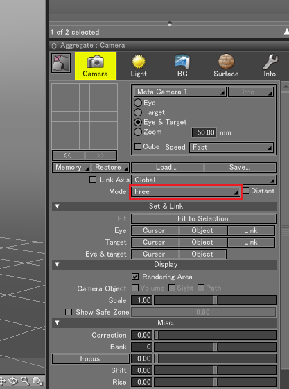
In the camera object's Free Mode, you will have a full object rotation, when you want to do the modeling in the perspective view, it comes in handy.
By repeating the techniques shown above, you will achieve the "fuselage" of the left body part of your dragon.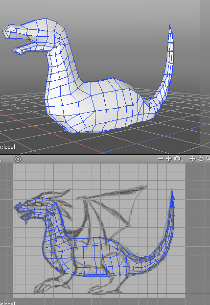
Mirroring
In order to mirror the left half of the dragon to create the right missing half, you will have to mirror on the X axis (from the front view window, position X=0).
You will also need to make sure that the vertices are all well aligned on the X=0 position. From the front view, select all the verteces to be placed in the center.
In the Modify>Tools, in "Other Tools", select "Align Vertices" and in thew "Tool Parameters" select, "Align Center x" and X Pos = 0. Then click the "Apply" button.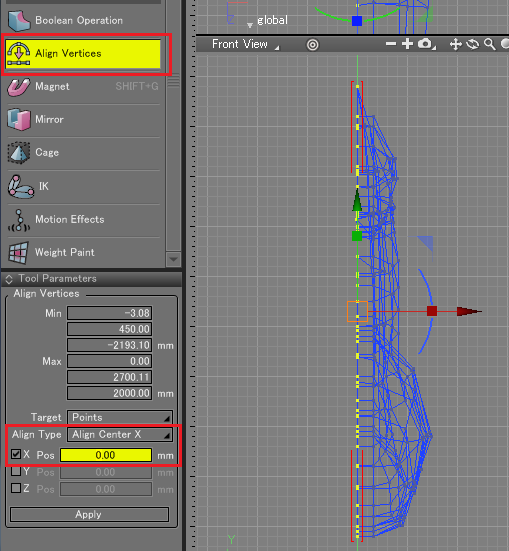
Here, the vertices are all aligned on the X=0 position.
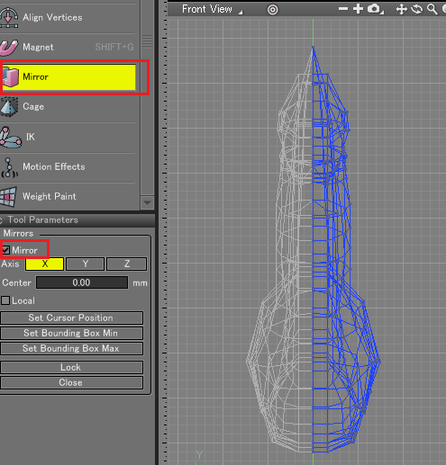
Under the Align Vertices tool you just used, there is the "Mirror" tool. Click it with your part to mirror selected and check the "Mirror" checkbox (X axis selected).
The mirrored part is still in a "virtual" state (light gray color).
If you move the left part vertices while mirroring, the movements will be synchronized on the right mirrored part.
After all your adjustments are done, you can click the "Lock" button of the Mirror "Tool Parameters" to transform the mirrored part into polygons.
Tips : Arrange your object with the Magnet tool
If you want to distort and move some vertices groups at the same time, the "Magnet" tool is very useful. Under "Align Vertices", select "Magnet" and adjust the parameters in the "Tool Parameters" window.
If you check the "Active Vertices Only" checkbox, only the selected vertices will be subject to deformation, otherwise, the whole object will be modified.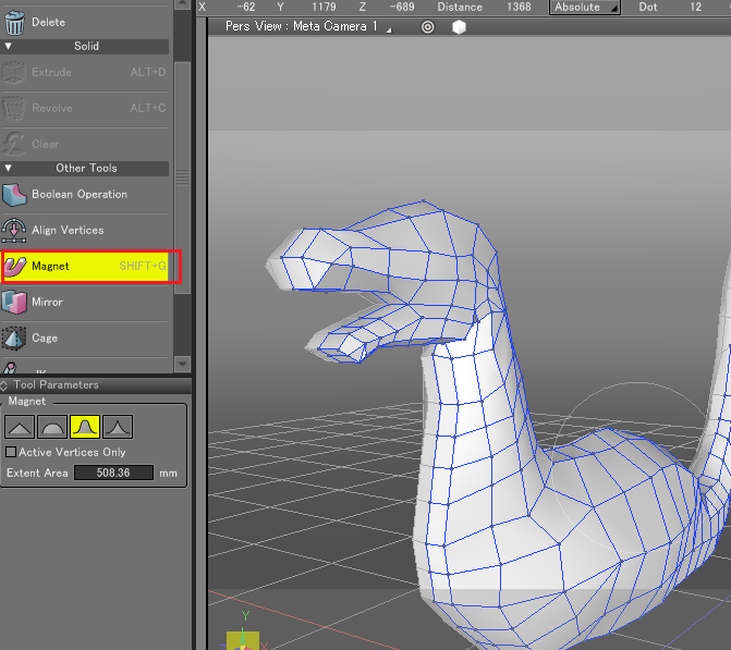
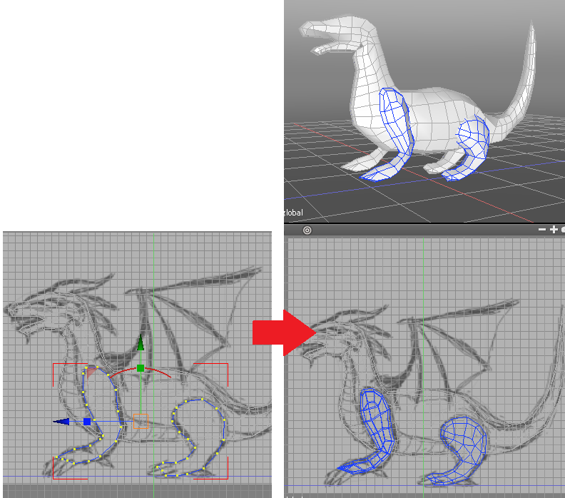
Feet Modeling
Lets keep on modeling the feet in the same way.
Create a new empty polygon mesh ("Create an empty polygon object"), you will extrude the outline again in order to create the surface.
Follow the same modeling process as the body modeling, you can hide the body part while modeling the wings and feet.
Wings Modeling
In order to create the wings frame, create an Open Line Object (in "Surface"), a Disk Object (that you will convert to a line object) and in the Plugins menu, use "Sweep Circle" on the created open line. After that, in the tool parameters, you can convert the shape to a polygon mesh. 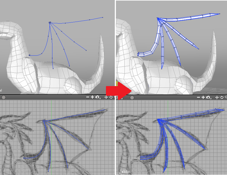
In order to create the membrane of the wing, you can use the "Bridge" tool of the Modify>Mesh>Edit toolbox.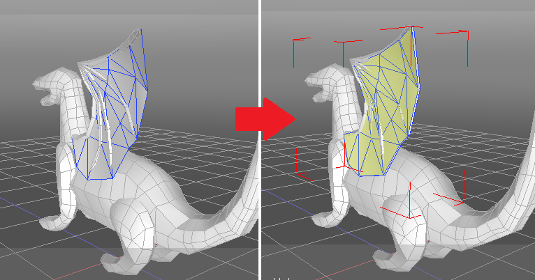
Combination of more than one polygon mesh
In this step, you will combine the body, the feet and the wing. Quit the mirror mode in order to have a better view of the useless polygons to be deleted.
Then, in the Edit mode of the Mesh menu, select " Merge selected polygon meshes together as a single mesh".
The objects will become one single polygon mesh.
The faces inside the model that are not visible will be deleted. Adding more faces will be done with the "Add' tools in the Mesh>Edit menu in order to keep one single object. 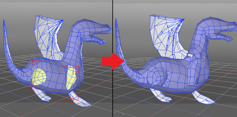
You can add more details such as horns and then, mirror again the part and "lock" it to a polygon mesh.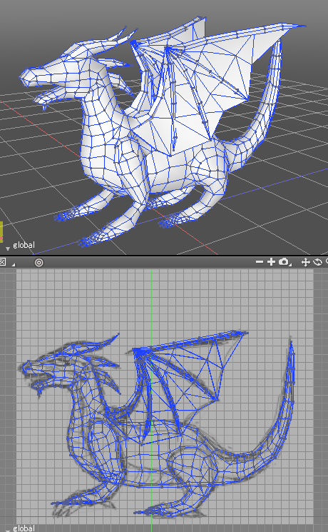
You are done with the modeling!
Click here to download the data!
by ft-lab